GPS
The GPS module features a u-blox NEO-M9N GNSS receiver with multi-constellation support and 25 Hz update rates. It includes an RP2040 microcontroller, CAN FD interface, external SMA antenna connection, and backup battery for fast satellite acquisition after power cycling.
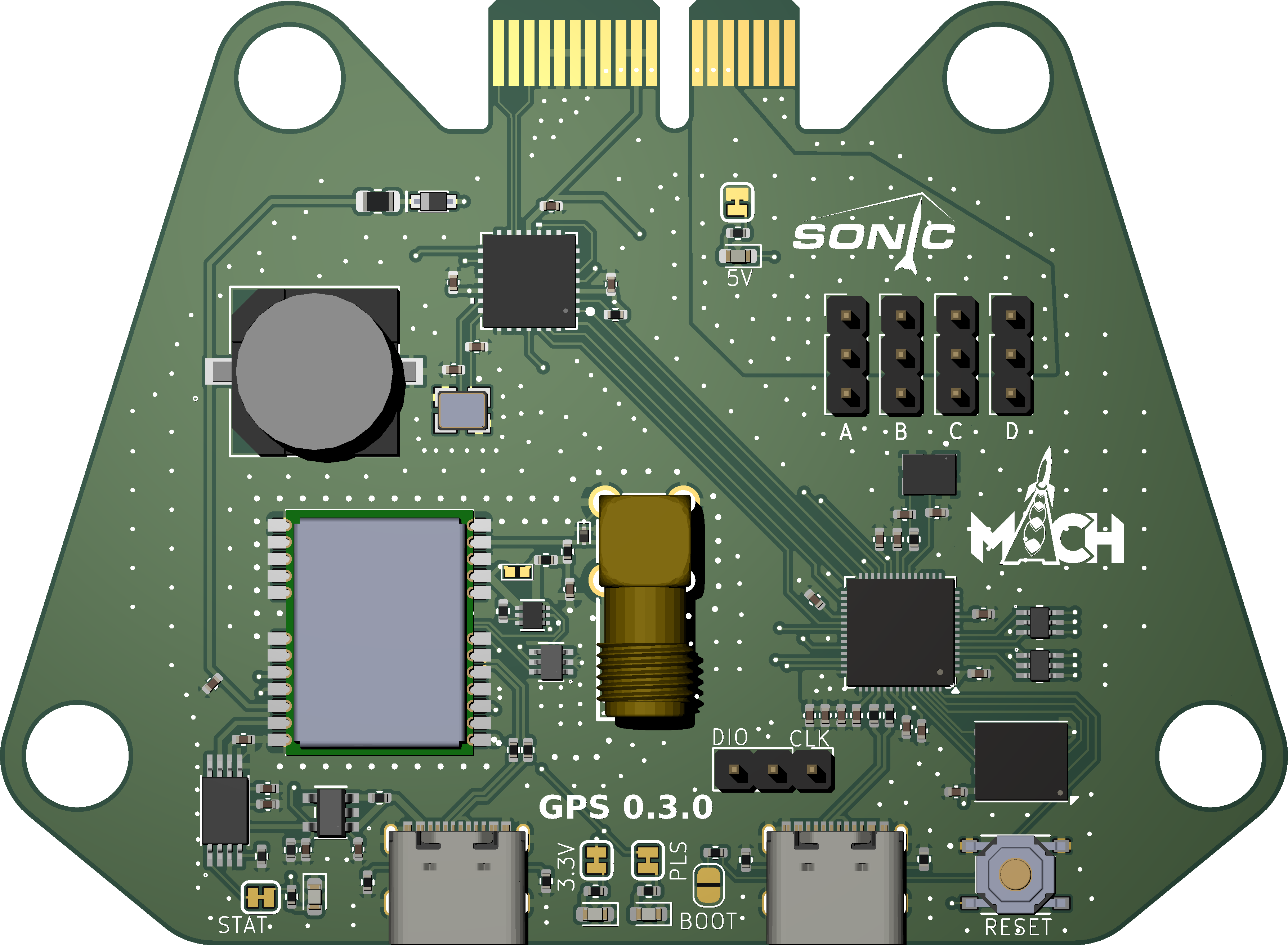
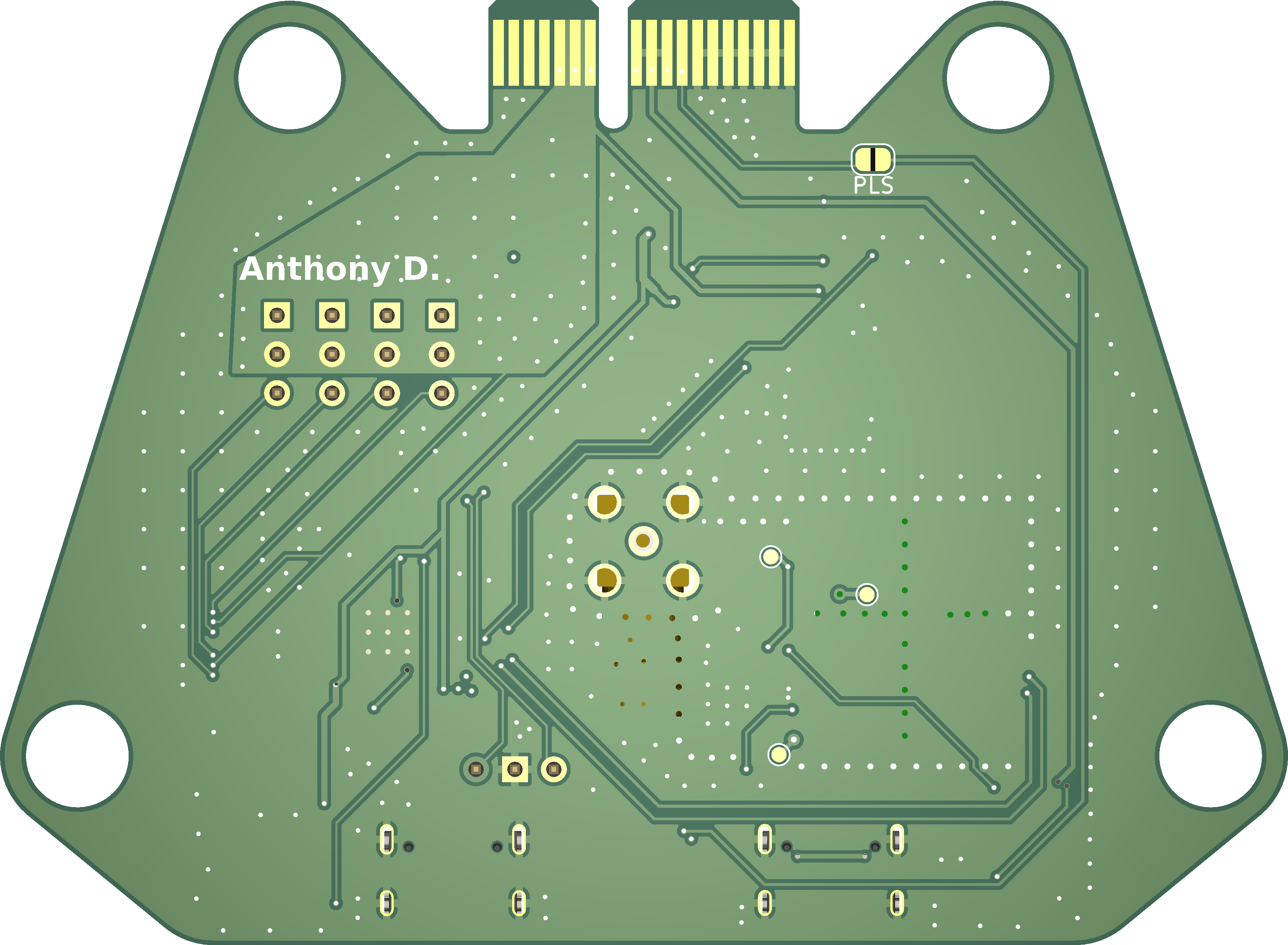
3D Render

Schematic


Footprint
Signal Filtering and Impedance Considerations
The purpose of the ferrite bead in the circuit is to act as a low-pass filter, effectively suppressing high-frequency noise that could interfere with the GPS signal. In this case, it is used instead of a traditional inductor to provide a compact and efficient filtering solution. Additionally, the circuit is designed to create an impedance mismatch, which can help control signal reflection or improve signal integrity in certain scenarios, depending on the design requirements.
Component Selection
In the M10S design, a ferrite bead was chosen over an inductor as a cost-effective solution, with the option to replace it in future iterations if needed. Additionally, a TVS diode was incorporated to ensure ESD protection, while a capacitor and resistor were added to meet the guidelines specified in section 4.3.4 of the integration manual.
Switch from MAX M10S to NEO-M9N
The MAX M10S GPS module was replaced with the NEO-M9N to enhance navigation performance. The NEO-M9N supports multiple GNSS constellations (GPS, Galileo, GLONASS, BeiDou) simultaneously, providing faster position acquisition, improved accuracy, and greater reliability. With update rates of up to 25 Hz, it delivers real-time position data critical for precise control and dynamic adjustments during use. Additionally, its suitable for high-altitude and high-velocity environments.
Choice of USB Hub Over Multiplexer
The decision to use a USB hub instead of a multiplexer (MUX) was driven by the need to support simultaneous access to the GPS and MCU. A USB hub allows concurrent bandwidth sharing across devices, whereas a MUX only connects one device at a time, requiring active switching.
Switching from USB Hub to Dedicated USB Port
Due to space constraints on the pcb, the USB hub was replaced with a dedicated secondary USB port. While this sacrifices concurrent device support, it simplifies routing, reduces component count.
SMA Connector Positioning for 90-Degree Antenna Bend
To accommodate the antenna’s 90-degree bend in the rack enclosure:
A right-angle SMA connector was in the middle of the board
The RF trace to the SMA connector follows a 50-Ω signle-coplanar design with a continuous ground plane beneath it and beside it to maintain signal integrity at 1.575 GHz (GPS L1 band).
Component Placement
RP2040 Microcontroller: Positioned near the USB ports to shorten high-speed traces.
CAN Transceiver: Isolated to prevent noise coupling.
Rechargeable 3V Lithium Cell Selection
A 6.8mm rechargeable lithium cell (MS621FE) was chosen over CR2032/CR1220 due to:
Size constraints: The 6.8mm fits better on the pcb. Rechargeability: Supports 500+ cycles, reducing long-term maintenance.
Trade-offs: Lower capacity (25 mAh vs. CR2032’s 225 mAh).
Migration to 4-Layer PCB
Upgrading from a 2-layer to a 4-layer board was driven by the NEO-M9N’s high-performance requirements:
Layer stackup: Signal/Ground – Ground – Power – Signal. This provides:
A dedicated ground plane for RF sections (GPS, SMA connector).
Improved EMI shielding and signal integrity for USB 3.0 and CAN FD traces.
Reduced parasitic capacitance in high-speed lines.
Thermal management: Inner power planes distribute heat from the CAN transceiver and RP2040.
Antenna Selection
The ANT-20087EB56 GPS antenna was purchased from DigiKey to confirm dimensions due to limited documentation. A right-angle SMA connector was used on the pcb to allow a 90-degree bend. Its whip format makes it ideal for the rack-mounted design. Physical measurements will be taken to confirm dimensions.
GPS Module Development Updates
Since the last update, several changes and improvements have been implemented in the GPS module design and development process:
Component Replacements
Due to supply chain constraints, some components were changed to similar alternatives, including some resistors and the battery holder. The primary GPS module (NEO-M9N) was also preordered due to lack of stock.
Advanced Antenna Integration
Research was conducted to allow more complex antenna features. This resulted in a detailed pdf, available as an attachment in the project repository:
BOM and Symbol Corrections
The Bill of Materials (BOM) had some corrections, particularly to fix inconsistencies coming from components initially sourced from EasyEDA since those components lacked readily available symbols and footprints. Adjustments were made to keep consistency in the BOM.
Manual Footprint Completion and Via Stitching
Footprinting was completed, alongside manual via stitching. In the future hopefully the plugin works.
New Logo and Silk Screen
The new logo for Sonic was added into the silkscreen layer of the PCB, resulting in a visually appealing and professional appearance.
Ergonomic and Accessibility Improvements
Minor adjustments included positioning the module name and boot select button at the front edge. This helps identify the module and provides convenient access for board reflashing.